A Quick Tour
This chapter provides a quick tour of the Real-Time Designer interface and introduces each of its features. It then describes how to take the initial steps to get up and running with the Real-Time Designer, and describes some of the basic tools provided to help you in the design process.
Main Window
The Real-Time Designer main window enables you to design a project to be deployed on an agent's computer.
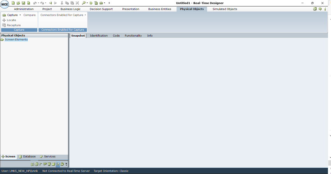
The main window opens automatically when Real-Time Designer is launched and remains open. The content of this window changes according to the module tab that you select.
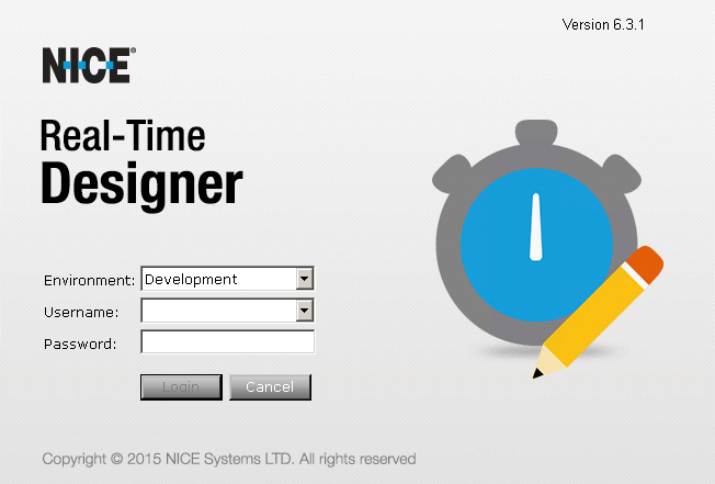
When you log in to Real-Time Designer, the domain you used to log in to Windows is automatically used. Optionally, you can specify the Active Directory domain to use for your Real-Time Designer login. To do so, enter <domain>\<username>.
When logging in to Real-Time Designer, select the environment to which you want to connect. The list of environments is based on the environment set in the Real-Time Designer configuration. To select a specific environment, select it from the Environment drop-down list. The Stand Alone option enables you to connect in standalone mode, meaning Real-Time Designer does not work with the server.
Main Window Components
The following components of the Real-Time Designer main window are common to all modules:
Module Tab Bar: Provides access to each of the Real-Time Designer modules. Click a tab to display the relevant module's window.
Module Tree: A hierarchical tree shows the relevant objects that can be defined in that module. The items that appear in each tree and the available options vary by module.
Quick Access Toolbar: Click the Quick Access icon  on the top left of the screen for quick access to standard generic options, such as New, Open, Save, Save As, Undo, Redo, Clone, Clipboard, and more. The same tools appear in all the modules.
Module Buttons: Provides options for creating and handling the relevant objects that can be defined in the selected module.
Module Work Area: Displays information and enables you to enter information that is relevant to the selected module.
Module Task Bar: You can also access the main window of each module by clicking the corresponding module icon. These icons appear in the left pane, at the bottom of the window.
Quick Access Icon: Provides quick access to general Real-Time Designer functions.
Info Tab: Displays general information about the selected Real-Time Designer object.
Status Bar: Provides status information about the current logged-in user, the connection to the Real-Time Designer/NiCE Perform server and the target orientation of the solution. The default orientation is Classic.

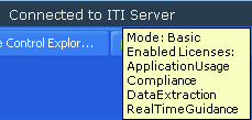
The status bar displays a tooltip when you hold the cursor over the ITI Connect server. The tooltip shows the licenses installed on the NiCE Interaction Management/Perform server.
Module Tab Bar
The Module tab bar provides access to the features of the respective Real-Time Designer modules:

|
Module |
Description |
Reference |
| Administration | ||
|
Project |
Enables you to open, validate, generate, and deploy Real-Time Designer projects. |
See Projects. |
|
Business Logic |
Enables you to define the logical entities that determine the behavior of Real-Time Designer according to your business requirements: business rules, workflows, and event handlers. |
See Business Logic. |
|
Decision Support |
Enables you to design decision support, which include KPIs and data collections that can both be used to generate reports. |
See Decision Support. |
|
Presentation |
Enables you to define the items that are displayed on an agent's and a supervisor's screen by Real-Time Designer: callouts, launch in contexts and alerts. |
See Presentations. |
|
Business Entities |
Enables you to design the data structures that represent the business entities of your organization and to instantiate them to represent the actual business entities of your organization. |
See Business Entities. |
|
Physical Objects |
Enables you to design physical objects, which represent the real physical entities (Screen Elements and data elements) of the applications and databases in the environment where Real-Time Designer operates. To design physical objects, you need to use connectors. The available connectors depend on the connectors selected during the Real-Time Designer installation. Depending on the installed connectors, different Screen Elements are captured. Each connector has Physical Object types, identification parameters, and relations that are specific to that connector. Each Physical Object type has specific properties, functions, and events. In some cases, a Screen Element connector can provide functionality that does not exist within Scene Composer connectors. In other cases, Scene Composer can provide functionality that does not exist with any of the Screen Element connectors. |
See Physical Objects. For a list of available screen connectors and extensions, see Connectivity IDD - RTI. |
|
Simulated Objects |
Enables you to capture objects using Surface Connectivity when the Real-Time Client and application are installed on different machines and cannot directly connect. Objects are captured by VDI (Virtual Desk Infrastructure). Available only for robotic solutions; cannot be used in attended solutions. |
See Simulated Objects. |
|
|
Displays information about Real-Time Designer. |
|

Info Tab
The Info tab appears in Real-Time Designer for every object that you define. It provides general information about the selected object.
When searching for an item or looking at the Referenced By attribute in the Info tab, Real-Time Designer shows the full object path to the object, including the containing module and the containing project.
To view the Info tab:
| 1. | Select a Real-Time Designer object in the tree. |
| 2. | Select the Info tab in Module work area. |
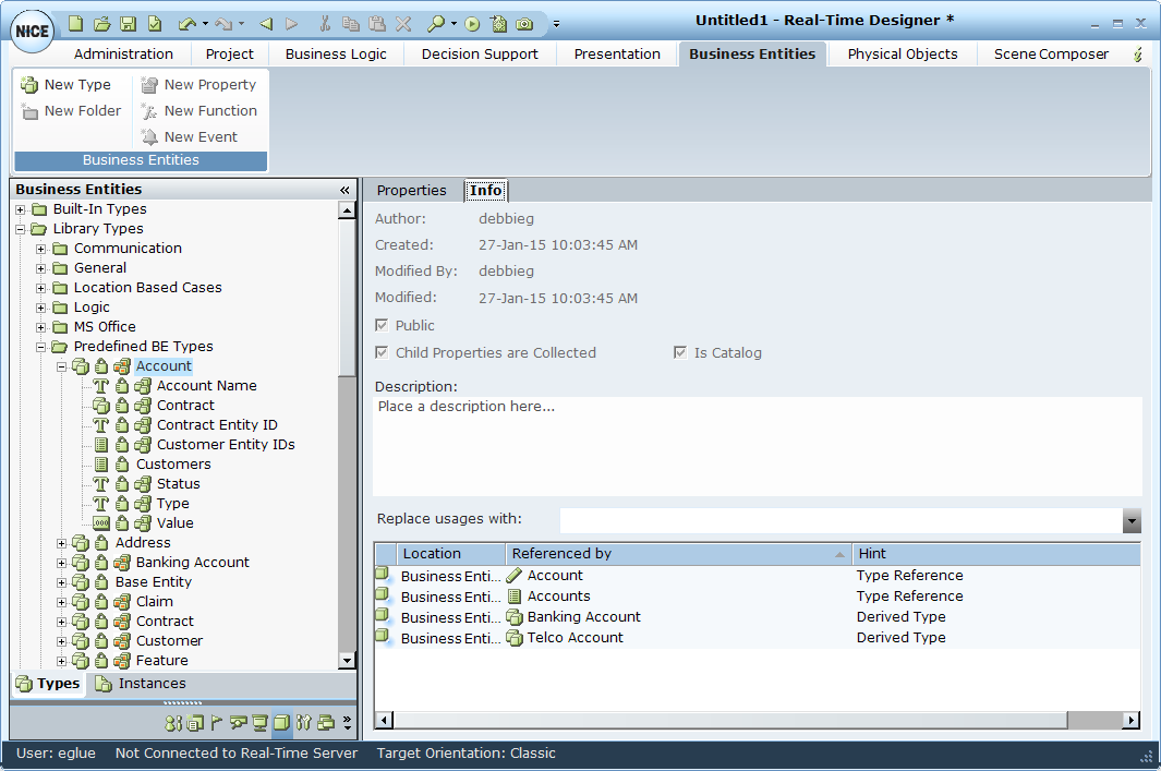
The following object parameters are displayed:
Author: The name of the logged in Real-Time Designer user who created this object.
Created/Modified By/Modified: The date and time when the Real-Time Designer object was created, by whom, and when it was last modified in Real-Time Designer.
Public: A public object creates an interface for other projects, meaning the object can be accessed by another project for which a reference to this project was defined. See References for a description of how to create a reference between projects.
Child Properties are Collected: Marks all the primitive properties of this element as collectable.
Is Catalog:
Description: Enter any textual description of this Real-Time Designer object.
Referenced by: Provides a list of the objects that use or reference this object.
If the Reference By option is disabled, the object is a private object in the Reference project.
Assignment Tool
The Real-Time Designer Assignment Tool helps you select the required options throughout the design process. It enables you to select from a variety of predefined Real-Time Designer elements and basic data types.
As you use Real-Time Designer to design the agent support experience, the Real-Time Designer Assignment Tool offers you the option to select any of the following: callouts, business entity types, business entity user instances, business entity properties, basic data types, such as Text, Date and so on, screen elements, workflows, event handlers, database connections and more.
In each field where the tool appears, it offers only the relevant types of information for your selection and enables you to drill down among objects. Selecting an option from the drop-down menu assigns it as the value of the field.
You can select an option in the following ways:
From the drop-down menu, select the relevant option. If the item that you select has child items, selecting it displays the next level of options from which you can select. If the item does not have a child item, then selecting it assigns that item to the field.
For example, selecting the Callouts options displays the names of the callouts defined in the current project. You can then select a specific callout name to assign it to the field.
Click the Force select (do not drill down) icon to select the displayed element, even if it has child elements. The Force select option can be used, for example, when selecting a list object that itself has functions that return a list of the same type, or when selecting a rule that has child rules.
This option only appears when applicable.
Start typing in the empty field to select from those options that start with the typed letters.
Click the folder icon  to move up a level in the hierarchy of options shown in this drop-down menu.
Click the ![]() icon to clear the current selection. This returns you to the window without affecting the value previously set in this field.
icon to clear the current selection. This returns you to the window without affecting the value previously set in this field.
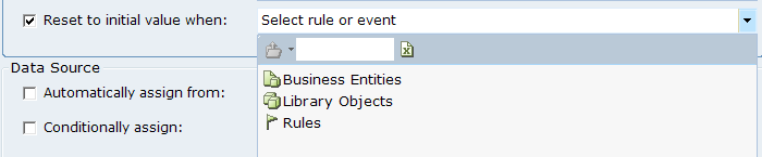
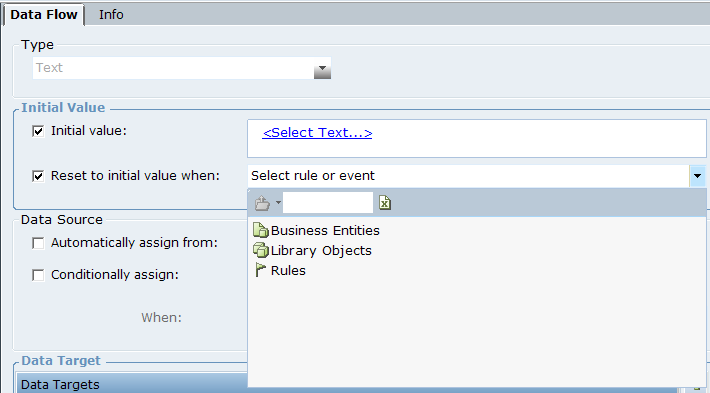
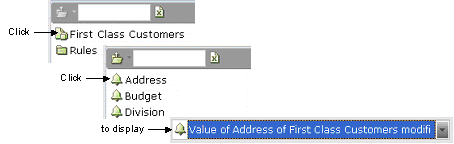
If you select a user instance called First Class Customers, its properties are offered for selection. You can then select a property to display it in the field. A short description of the selection appears in the field.
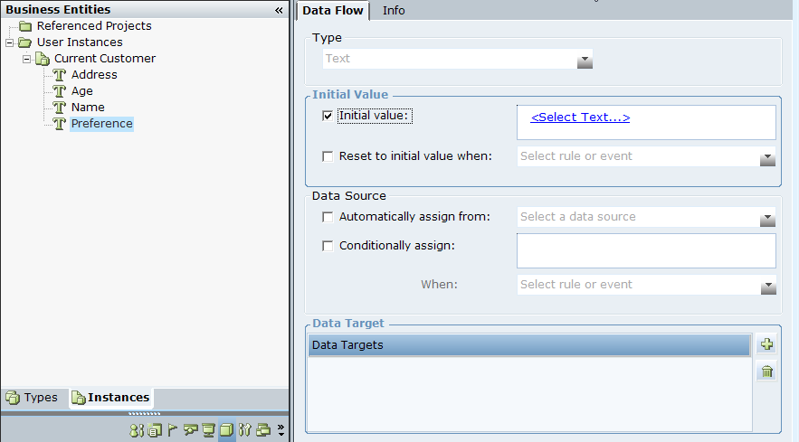
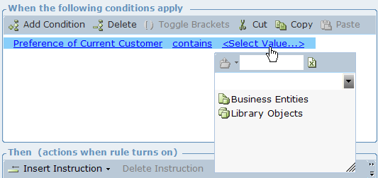
If you are setting an initial value for the Preferences property of the Current Customer user instance, which is selected in the User Instances tree (as shown below), select Initial Value to activate this field.
Click the <Select Text> link to display a drop-down menu of the types of objects you can select in Real-Time Designer:
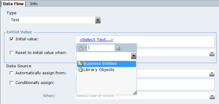
Select the Business Entities user instance to display a list of the business entities defined in Real-Time Designer.
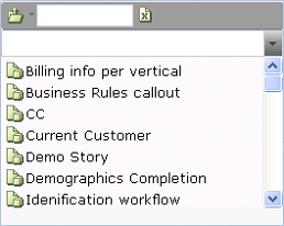
Select Demo Story to display a list of properties defined for that business entity.
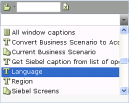
Select Language to specify the preference of this customer. The Initial Value of that user instance is displayed, showing that you selected the Language Property from the business entity Demo Story:
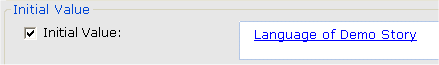
On the Real-Time Client, during runtime, the value in the Language Property of Demo Story will be assigned as the Initial Value of the Preference Property of the Current Customer user instance.
You can also enter an empty or blank value in <Select Text> link. To enter empty or blank value, click the value selection text box and press Enter. This is applicable where a parameter of a function accepts text value.
![]()
Boolean Statement Editor
The Boolean Statement Editor helps you to define Boolean statements, which are made up of conditions. As you use the Real-Time Designer to design the agent support experience, the Real-Time Designer Boolean Statement Editor Tool enables you to:
-
Select or define a Boolean condition expression. For example:
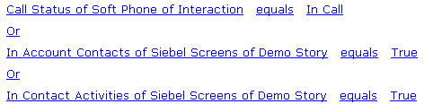
The conditions and the relationship between them (Or or And) comprise a statement. An Or relationship means that at least one of these conditions must exist for the statement to be true.
-
Select an existing condition or business rule. Business rules can be defined and edited, as described in Business Rules.
-
Select an event handler. Event handlers can be defined and edited, as described in Event Handlers.
Working with Conditions
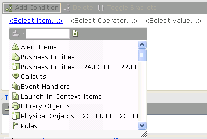
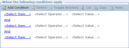
The Real-Time Designer provides a variety of predefined condition templates that you can use when defining a condition. The most basic one is displayed when you click Add Condition on the Rule Editor tab. This condition specifies when a business rule is fulfilled.
<Select Item…> <Select Operator…> <Select Value…>
Each of the elements enclosed in brackets is a link through which the Real-Time Designer gives you relevant options for selection. This simple expression enables you to select an item, a value and an operator with which to compare the item and the value.
The same procedure is applicable when you define a condition elsewhere in the Real-Time Designer. For details on using Add Condition to add a new condition, see A Quick Tour.
Defining a Basic Condition
This section describes how to define a basic condition.
To define a condition:
| 1. | Click Add Condition to add a basic condition template. For example: |
<Select Item…> <Select Operator…> <Select Value…>

This simple expression enables you to select an item, a value, and an operator with which to compare the item and the value.
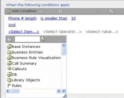
| 2. | The <Select Item…> link is automatically selected and a standard Real-Time Designer Assignment Tool drop-down list appears. To see it again if it closes, click the <Select Item…> link. |
A list of the types of objects that can be selected, such as business entities, callouts, and alerts, is displayed in the Real-Time Designer Assignment Tool, as described in Assignment Tool.
Examples:
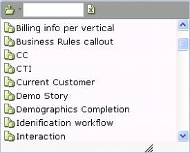
If you select Business Entities, a list of all previously defined business entities appears:
If you select Current Customer, a list of the properties of the Current Customer business entity appears:
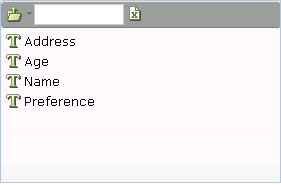
If you select Preference, the condition appears:

The words Preferences of Current Customer indicate that the Preferences property belongs to the Current Customer business entity. You can click the link to modify the entry.
| 3. | To select an operator, click <Select Operator…>. A drop-down menu of comparison operators appears: |
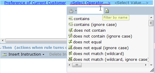
This operator is used to compare the selected item with the value you select in the next step.
For example, the following is shown if you select equals:

| 4. | Click the <Select Value…> link to display a standard Assignment Tool drop-down menu: |
This value is compared to the selected item according to the operator selected in the previous step.
The format of the condition template changes according to the option you select after clicking the <Select Item…> link.
The following table shows the data type conversions that can be performed in the Action Editor or business entity property by invoking an explicit convert <type> to <type> function.
|
Source |
Text |
Integer |
Decimal |
Boolean |
Date-Time |
|
Target |
|||||
|
Text |
Yes |
Yes |
Yes |
Yes |
Yes |
|
Integer |
Yes |
Yes |
Yes |
Yes |
No |
|
Decimal |
Yes |
Yes |
Yes |
Yes |
No |
|
Boolean |
Yes |
Yes |
Yes |
Yes |
No |
|
Date-Time |
Yes |
No |
No |
No |
Yes |

Compounding a Basic Condition
This section describes how to compound a basic condition with an And or an Or statement.
To compound a basic condition with an And or Or statement:
-
After you define a basic condition, click Add Condition again to add another condition.
This condition is automatically added with an And condition, meaning that both condition statements must exist for this condition to be fulfilled.
-
If you want to change the And condition to an Or condition, click the And link and select Or. This means that either the first condition or the second condition must exist for the condition (as a whole) to be fulfilled.
-
Repeat these steps to compound as many conditions as you need.
Using Logical Expression Brackets
When you define more than one condition, logical expression brackets can be used to group conditions together.
To use logical expression brackets:
-
Highlight two or more conditions to be grouped in the brackets.
-
Click Toggle Brackets to enclose these conditions in brackets.